C280-8 Offshore Generator Set

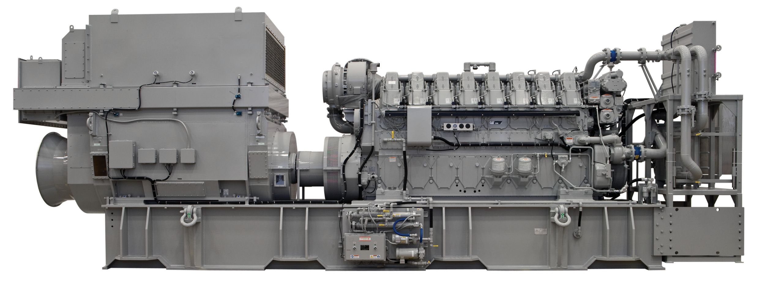
The C280-8 generator set incorporates years of proven success of the 3600 engine with the latest technology in electronics. The result is a fully integrated solution that is ideal for offshore operations.Ideal applications for the C280-8 offshore generator set are main power on-board drilling and production vessels and platforms.Complete package offerings are MCS type-approved and compliant with IMO Tier II emissions standards, making integration of the Cat C280-12 generator set into the vessel a simplified operation.Cat generator sets are backed by the worldwide network of Cat dealers ready to support your operation with technical support, service, parts, and warranty.Cat C280-8 offshore generator set. Ratings: 2208-2600 ekW (2760-3714 kVA) @ 50/60 Hz (1000/900 rpm). IMO Tier II emissions compliant.

Get a Quote
Minimum Rating 3084 kV·A
Maximum Rating 3634 kV·A
Emissions IMO Tier II/EPA Marine Tier 2
Displacement 9031 in³
Oil Change Interval 1000 h
Weight 108027 lb
Generator Set Control Generator Monitoring System (GMS)
Aspiration Turbocharged-Aftercooled
Stroke 11.8 in
Engine Control Electronic ADEM™ A3
Fuel System EUI
Bore 11 in
Length 320.5 in
Height 134.1 in
Width 91.6 in
Cooling System - Engine 140 gal (US)
Lube Oil System - Refill 289 gal (US)
Product Consist
  • The engine is a turbocharged, aftercooled, four-strokecycle-diesel, electronic unit injection engine with a280 mm (11 in) bore by 300 mm (11.8 in) stroke. SAEstandard rotation is counterclockwise as viewed from therear of engine flywheel.
Emissions Certifications
  • GL and CCS approved IMO certificate — includesstatement of compliance or Engine International AirPollution Prevention (EIAPP) certificate, supplied by theRecognized Organization (RO) where available, andtechnical file to be kept on board per IMO regulations.
Marine Certification Society type-approval
  • ABS, BV, CCS, DnV, GL, LRS
  • Spray shielding to meet SOLAS regulations for flammablefluids
European Certifications
  • Declaration of Incorporation for EU Machinery Safety
  • Directive and EU Low Voltage Safety Directive
Air Inlet System
  • Fresh water aftercooler, corrosion resistant coated (airside)
  • Air inlet shutoff
  • Turbocharger, rear-mounted, oil lubricated
Control System
  • Single Cat ADEM A3 electronic engine control module withelectronic unit injector fuel system, rigid wiring harness(10 amp 24V power required to drive electronic enginecontrol modules)
Cooling System
  • Gear-driven jacket water (JW) pump
  • Gear-driven separate-circuit aftercooler/oil cooler (AC/OC) pump
  • Engine coolant water drains
Exhaust System
  • Dry, gas tight exhaust manifold
Fuel System
  • Distillate fuel (requires viscosity ranging from 1.4 cStto 20 cSt at 38°C)
  • Fuel pump, gear-driven
  • Fuel transfer pump (mounted on left-hand side)
  • Duplex fuel filters, rear-engine-mounted
  • Electronically controlled unitinjectors
Lube system
  • Centrifugal oil filters with single shutoff, service-side enginemounted on cylinder block inspection covers (includesinstalled oil lines and single shutoff valve), filters centrifugebypass oil from the main lubricating oil pump (can be servicedwith the engine running)
  • Oil filler and dipstick
  • Oil pressure regulating valve
  • Dry engine-mounted sump system that gravity feeds intobase assembly integral sump
  • Engine-mounted duplex oil filter
  • Intermittent air prelube
  • Continuous electric prelube
  • Redundant prelube with continuous electric prelube andintermittent air prelube backup
  • Oil pan drain valves
  • Electric continuous prelube pump
  • Lube oil heater
  • Oil pump - gear drive
Protection System
  • Crankcase explosion relief valves
  • Alarm and shutdown during abnormal operation
Instrumentation
  • PLC-based system provides protection, monitoring, andcontrol housed in a NEMA 4 (IP66) enclosure.
General
  • Service Literature
Air Inlet System
  • 90° adapter and straight adapters for air inlet to turbochargerAir cleaners
  • Air cleaners with Cat dry paper filter elements (approximately99.9% efficient at filtering SAE fine dust)
  • Soot filter
Control System
  • 4-20 mA load feedback signal
  • Load sharing module
  • Direct rack module
Cooling System
  • Separate Circuit Aftercooler (SCAC)
  • Customer water connections
  • Jacket water thermostats
  • AC/OC thermostats
  • Accessory module-mounted high volume expansion tank
  • Jacket water heater
  • Heat recovery connections and thermostats for use withwater maker system
  • ANSI connection adapters
Exhaust System
  • Exhaust manifold shields
  • Vertical or 30° outboard exhaust orientation options
  • Exhaust outlet expanders and weld flanges
Fuel System
  • Manual fuel priming pump
  • Duplex primary fuel strainer
  • Flexible fuel hose connections
Lube System
  • Dry engine-mounted sump system that gravity feeds intobase assembly integral sump
  • Engine-mounted duplex oil filter
  • Intermittent air prelube
  • Continuous electric prelube
  • Redundant prelube with continuous electric prelube andintermittent air prelube backup
  • Oil pan drain valves
  • Electric continuous prelube pump
  • Lube oil heater
Protection System
  • Wiring meets MCS requirements
  • Upgrade PLC monitor to industrial PC
  • Upgrades AC/OC, JW and start air pressure from contactorsto transducers
  • Raw water/sea water pressure transducer
  • Modbus communication
  • Beacon and horn
  • Single engine remote display monitor
  • Emergency pump start signal
  • Cabinet cooler
  • Generator power monitoring
  • Remote relay panel
  • Turbocharger speed sensors
  • Cylinder pressure relief valve
  • Oil mist detector
  • Flywheel and damper guards
Mounting System
  • Base aseembly
  • Vertically-restrained vibration isolators and weld plates
Starting System
  • Single turbine air starters
  • Boost control valve for extremely cold ambient conditions
  • Air start pressure reducing valves
General
  • Torsional couplings
  • Mounting groups for engine, generator, and base
  • Accessory module to mount attachments such as theexpansion tank, heat exchanger, instrument panel andengine controls, annunciator panel, alarm and shutdowncontactors, fuel strainer
  • Flywheel
  • Engine barring device options:
  • One-year storage preservation
  • Oceanic transportation shipping protection (shrink wrapand tarp)
  • Engine testing — certified dynamometer test, fuelconsumption test, rated speed performance test, overloadtest, minimum power setting, peak firing pressure test,turbo work cert and crankshaft work cert
  • Standard and project-specific witness testing
  • Spare parts kits
Literature
  • Project-specific installation drawings
  • Electrical schematics and P&ID drawings